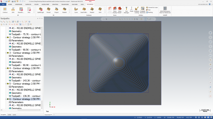
A look at Contour transition types
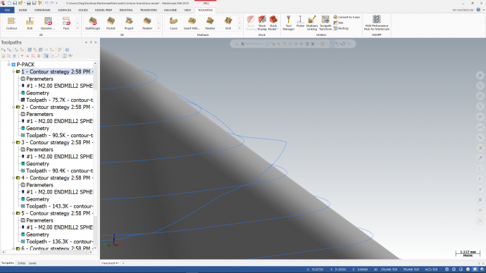
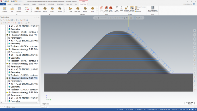
The Contour strategy in HSM Performance Pack is designed to give you an optimal finish for steep regions in your geometry. It is typically applied to areas where the slope exceeds an angle of 30 degrees. The Contour algorithm slices the geometry into horizontal layers. At every layer the toolpath machines along the edge of the two-dimensional geometry and then transitions to the next layer.
The Contour strategy supports the following transition types.
- Straight line
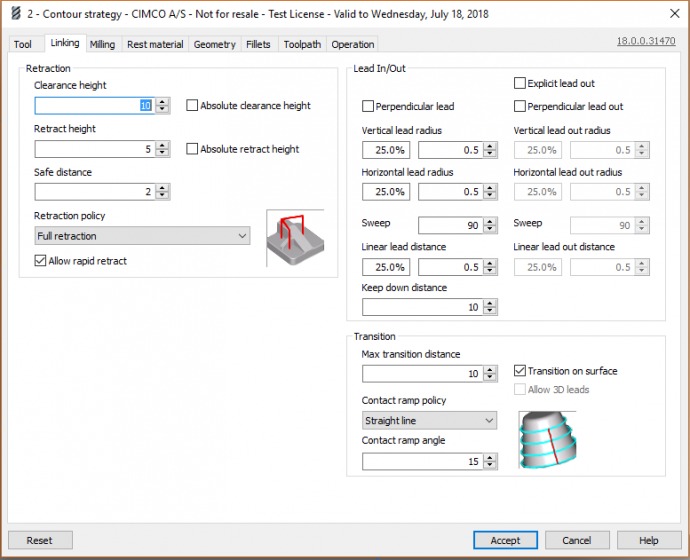
Creates a side projection of the segment that connects the top and bottom paths. The angle of the transition to the top and bottom paths can be controlled using the option “Contact ramp angle”. - Curve
Creates a side projection of a smooth curve (arc-line-arc) that connects the top and bottom paths. The angle of the transition to the top and bottom paths can be controlled using the option “Contact ramp angle”. - Loop
Creates a smooth curve that connects the top and bottom paths and that does not touch the surface, except at the start and end points. Length can be controlled by the option “Max transition distance”. - Disabled
Disables all transitions and only lead-in, lead-out and retract are used.

Transition types: Straight line, Curve and Loop
Experiences with Straight line and Curve
In most cases the Straight line and Curve transitions perform really well and provides a great end result. However, in our tests we noticed that, in some cases, these transitions would leave marks on shallow areas of the machined part. To solve this problem, we programmed the Straight line and Curve transitions to first try and move away from the surface in such areas and then ramp down.
This default behaviour can, of course, be overridden in the configuration using the option “Transition on surface” which forces the tool to stay in touch with the surface.
Changing the plane when using Loop
Loop transitions by default leave and approach the surface in the 0xy plane. To instead use the plane perpendicular to the surface in touch points, the option “Allow 3D leads” can be enabled. This helps avoid scratching of flat surfaces, but also affects the lead-in and lead-out.
5-axis recommandations
When 5-axis tilt is enabled, we recommend only using the transition types Loop or Disabled. Our tests have shown that other transitions might leave marks on the surface due to significant changes in the tool axis between start and end positions.
Transitionless with Spiral
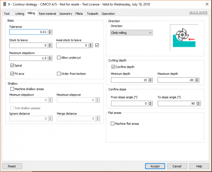
For “single core” or “single cavity” parts, the best surface quality might be achieved by using the Spiral option under the Milling tab. With Spiral, the toolpath moves downwards on the part in a steady spiral, without any transitions. Through this transitionless contour, the strategy leaves no transition marks on the part, creating a much nicer finish than a conventional contour operation. In addition, the machine dynamics are maintained at all times, since the depth changes are much more gradual.
To test the difference between various settings, please download our demo file “Contour transitions”.
Please see the documentation for more information about the Contour strategy.


