|
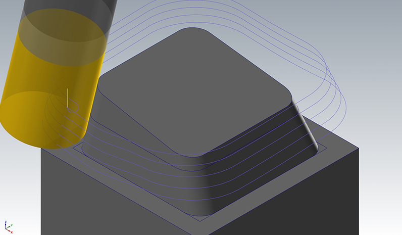
The Swarf finishing strategy provides a quality that is near perfect. Unlike other strategies, the Swarf strategy utilizes the side of the tool for machining and leaves a surface finish without any stepover or stepdown marks. Due to the nature of Swarf, there are some limitations to where the strategy can be applied.
Usability
In HSM Performance Pack it is easy to do selections on the geometry and the Swarf strategy supports the modes Contours and Surface.
The Contours mode requires that bottom and top contours are selected. Synchronization between the selected contours is automatically created and a toolpath is generated. The direction of the toolpath is similar to that of the bottom contour. The direction of the top contour is changed automatically if it does not match the direction of the bottom contour.
When using Contours mode, Swarf will generate nice and smooth toolpaths in most cases. However, since the surface is not taken into consideration, gouges might be created against the surface. Synchronization of contours might also fail in situations where the selected contours are too complicated.
Surface mode requires bottom, top contours and drive surface between them. Surface mode solves the issues that might occur in Contour mode by letting the user specify Drive and Check surfaces. Drive surfaces are normal machining surfaces used for synchronization between contours. The toolpath does not gouge against the contours and drive surfaces and
will attempt to machine with the side of the tool where possible. Check surfaces are used only for avoiding gouges and the toolpath is simply trimmed if the tool starts touching any of the specified Check surfaces.
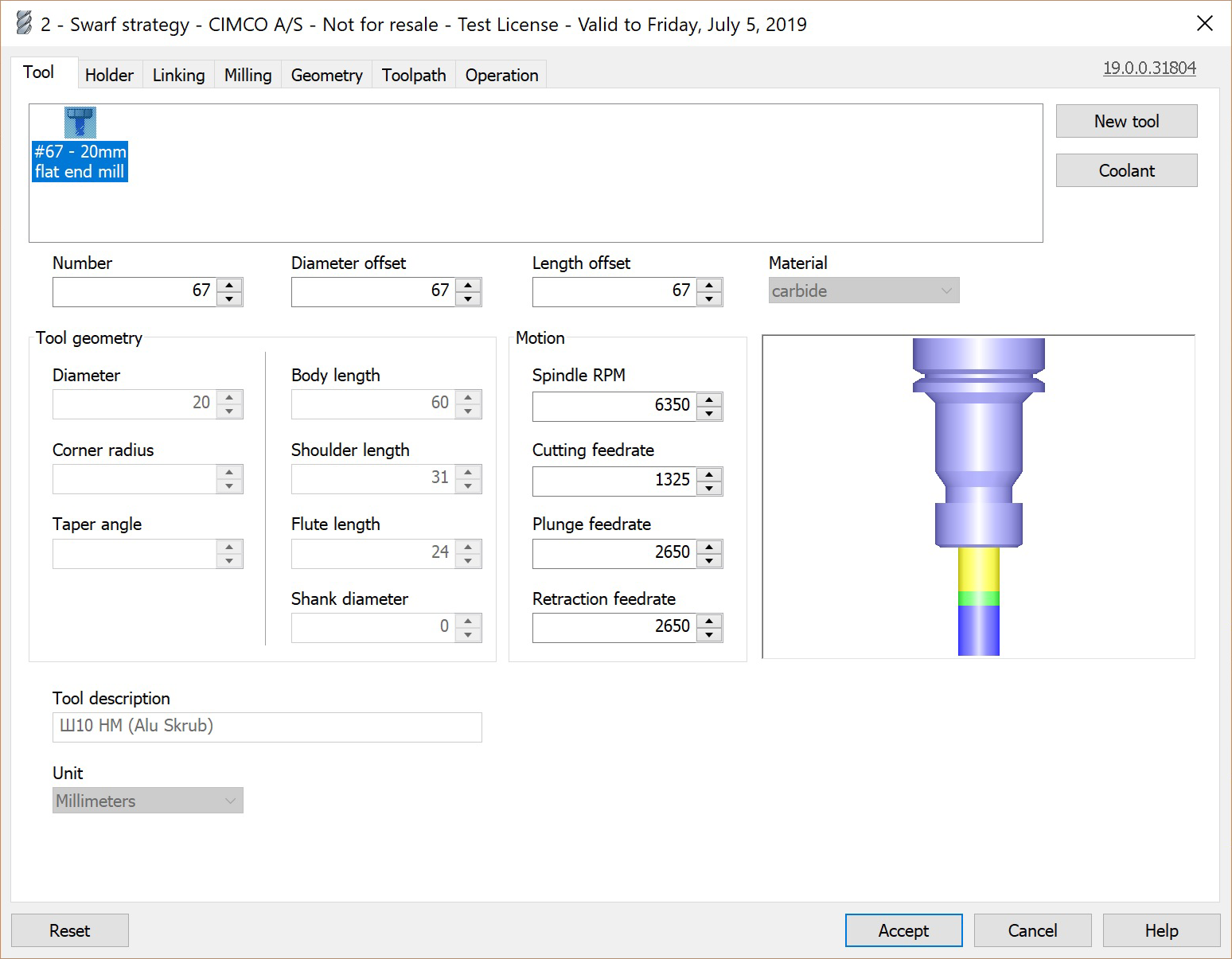
In the tool area, at the top of the dialog, new tools can be created and existing tools can be selected. New tools can be created using either the New tool button, on the right, or by using the right-click menu. When a tool is selected, the fields below automatically update to show the values associated with the selected tool.
The tool drawing at the right side of the dialog shows how the selected tool looks. Each time a value in a field is changed and the field is exited, the drawing is automatically updated to reflect the changes.
The flute length does not have an effect on the shape of the cutter paths unless a taper angle is applied. Tapered tools add the shape of a cone of the given taper angle from the vertical axis. The bottom of the (truncated) cone is tangential to the shape at the tip, and the top is at the flute length above the tip. For tapered tools, the tool definition is straightforward for ball nosed and flat-bottomed tips, but for bull nosed tips the standard convention is more complicated: the shaft diameter refers to the diameter of the bottom of the conical surface and not the diameter of the virtual toroidal shape that would be within the tapered shape.
|
|
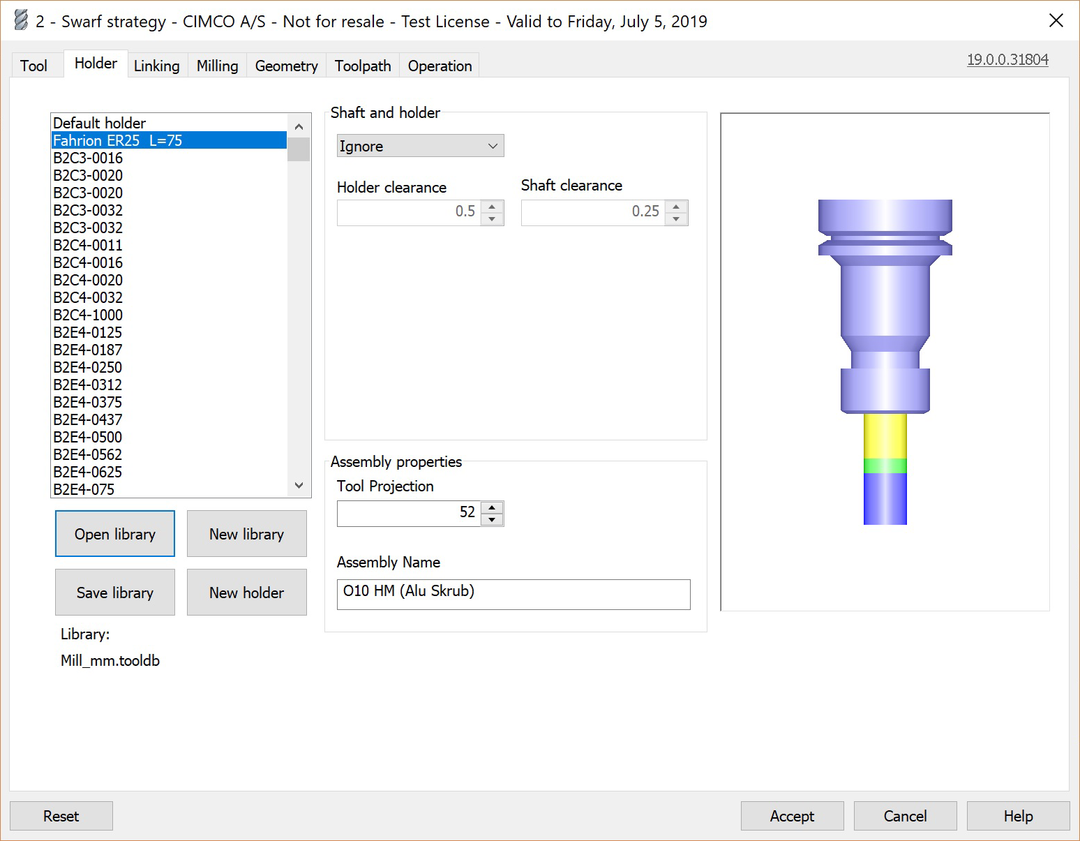
In the section Shaft and holder you can define holder and shaft collision checks and how the toolpath should respond to detected collisions. In particular, this is where you can define to tilt the tool in case of a collision, effectively creating a 5-Axis toolpath.
Note that these collision checks require additional calculation time when the toolpath is generated, but ensures that the shaft and holder do not collide with the part if used.
The following parameters can be set to control the collision detection:
Collision detection policy
The dropdown menu lets you select how HSM Performance Pack should react to a detected holder collision. The following options are available (depending on the selected strategy):
Ignore
With the option Ignore, collisions between the shoulder, shank, holder and the work piece are ignored.
Detect length
With the option detect lenght, HSM Performance Pack checks toolpath and suggests a flute length to the user for which any holder collisions are avoided.
A warning such as the following will be provided to suggest a tool:
“Warning: Tool flute must be increased by 53.04 to avoid holder gouge.”
Fail on collision
With the option fail on collision, the toolpath generation fails in case the software detects a holder collision.
The following is an example error which is provided to help the user in removing the gouge:
“Error: Holder Gouge detected at point (37.7439,-57.5288,0), tool axis: (0,0,1), linking path #102”
Trimming
When the trimming option is selected, toolpath will be trimmed away in areas of holder collisions.
Holder clearance
The Holder clearance defines the safety distance between the holder and the stock. If the holder gets closer to the part (or stock) than this distance, it will be treated as a collision.
Shank clearance
The Shank clearance defines the safety distance between the shank and the stock. If the shank gets closer to the part (or stock) than this distance, it will be treated as a collision.
|
Clearance height
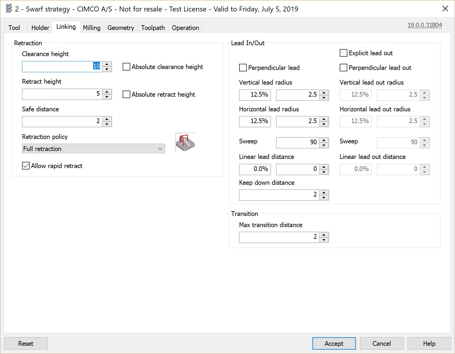
The Clearance height defines the first height to which the tool moves before the start of the toolpath. The height is relative to the top of the surface to be machined.
The field Absolute clearance height can be enabled to define an absolute Z value instead.
Retract height
The Retract height defines the height to which the tool retracts between cutting passes. The linking moves at this height are carried out at rapid speed. The height is relative to the top of the surface to be machined.
The field Absolute retract height can be enabled to define an absolute Z value instead.
Safe distance
The Safe distance defines the minimum distance between the tool and the part surfaces during shortest path retract moves. This distance is measured after the stock to leave has been applied, so if a negative stock to leave is used, special care should be taken that the safe distance is large enough to ensure that no collisions occur.
Retraction policy
The Retraction policy determines how moves between cutting passes are done. Shortest path is the shortest possible path (which often includes moves in all three axes), Minimum retraction is straight up to the lowest height where the tool will be clear of the part (by safe Z distance), and Full retraction is to the clearance plane.
Allow rapid retract
By enabling Allow rapid retract, vertical retract moves will be carried out at rapid speed. If this is not enabled, retracts will be carried out at the lead-out feedrate.
Explicit lead out
By enabling Explicit lead out you can define the lead out parameters independently from the lead in parameters. If not enabled, the lead out parameters will be identical to the lead in parameters.
Perpendicular lead
By enabling Perpendicular lead you can define that a movement which is perpendicular to the lead-in/out arc should replace tangential extensions of arcs.
Perpendicular lead out
By enabling Perpendicular lead out you can define that a movement which is perpendicular to the lead out arc should replace tangential extensions of arcs.
Vertical lead radius
A lead-in or out movement generally consist of three components. The horizontal lead-in/out arcs which is located in the perpendicular plane to the tool start axis and leading smoothly into or away from the toolpath, followed by a linear segment in the same plane, and a vertical arc connecting the linear segment with the retract movement.
Vertical lead radius defines the radius of the vertical arc component of the lead-in/out movement. The radius can be specified as a percentage of the tool diameter or as an absolute value.
Vertical lead out radius
Vertical lead out radius defines the radius of the vertical arc component of the lead-out movement. The radius can be specified as a percentage of the tool diameter or as an absolute value. You need to enable Explicit lead out in order to specify a separate vertical lead out radius. Otherwise, the same radius will be used for lead-in and lead-out.
Horizontal lead radius
Horizontal lead radius defines the radius of the horizontal arc component of the lead-in/out movement. The radius can be specified as a percentage of the tool diameter or as an absolute value.
Horizontal lead out radius
Horizontal lead out radius defines the radius of the horizontal arc component of the lead out movement. The radius can be specified as a percentage of the tool diameter or as an absolute value. You need to enable Explicit lead out in order to specify a separate horizontal lead out radius. Otherwise, the same radius will be used for lead-in and lead-out.
Sweep
Sweep defines the sweep angle between the linear segment component of the lead-in/out movement and the toolpath.
Sweep (lead out)
Sweep (lead out) defines the sweep angle between the linear segment component of the lead out movement and the toolpath. You need to enable Explicit lead out in order to specify a separate lead out sweep angle. Otherwise, the same angle will be used for lead-in and lead-out.
Linear lead distance
Linear lead distance defines the length of the linear segment component of the lead-in/out movement.
Linear lead out distance
Linear lead out distance defines the length of the linear segment component of the lead-in/out movement. You need to enable Explicit lead out in order to specify a separate linear lead out distance. Otherwise, the same distance will be used for lead-in and lead-out.
Keep down distance
The Keep down distance defines a length below which retracts are avoided. This means that lead-in and lead-out moves are still generated below this length, but the tool is only lifted up slightly.
Max transition distance
Use the parameter Max transition distance to define a maximum allowed length for transitions between cutting passes. If the distance between two passes is greater than the Max transition distance, the tool retracts or is lifted up and a lead-out and lead-in are generated.
|
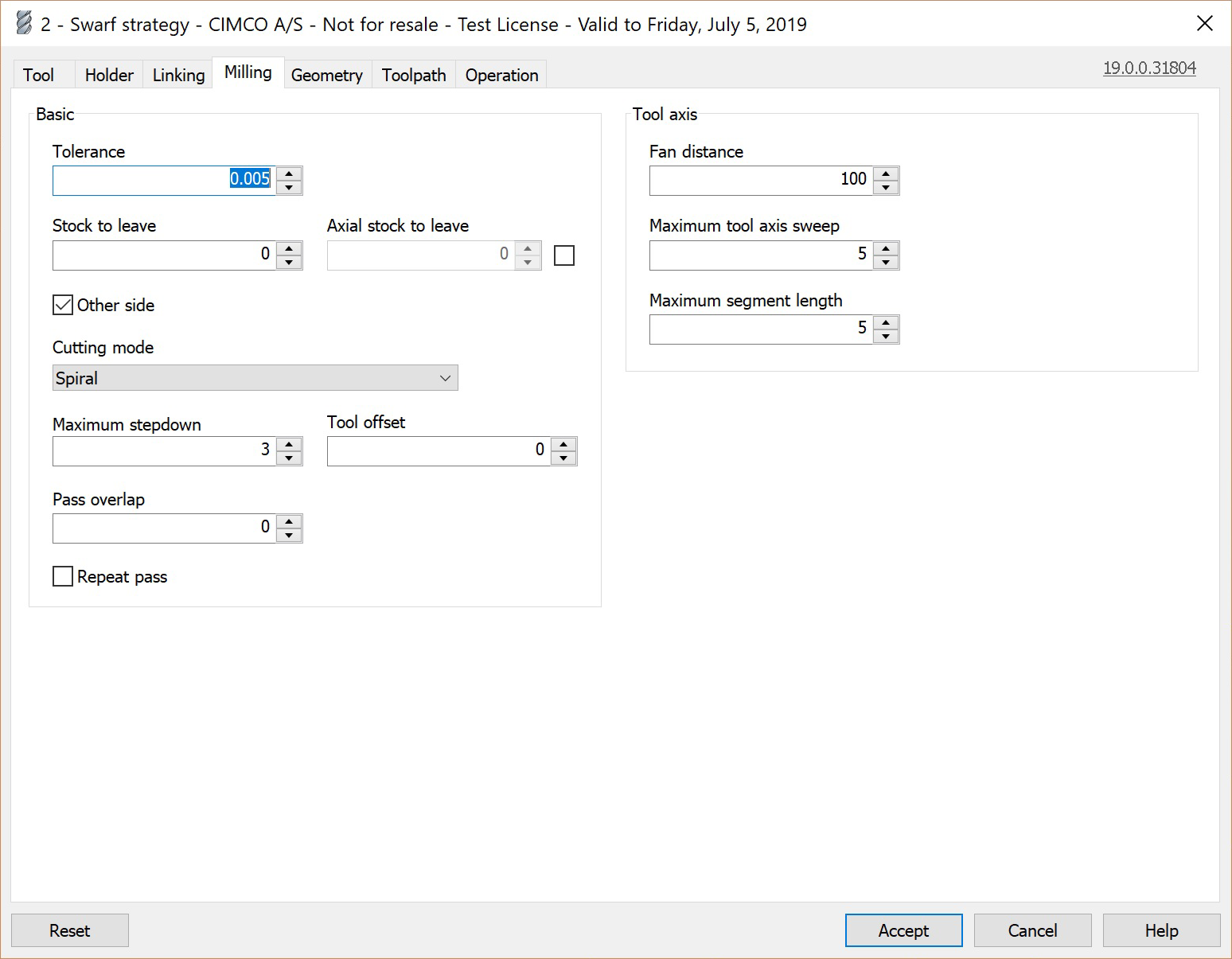
Tolerance
Tolerance defines the maximum value the toolpath is allowed to deviate from the surface of the input geometry. A small tolerance value yields more precise toolpaths at the expense of longer computation times.
Stock to leave
Stock to leave defines the stock to leave in the plane perpendicular to the tool direction by offsetting the tool away from walls.
Axial stock to leave
Axial stock to leave defines the stock to leave in the Z-direction, i.e. in the direction along the tool axis. Axial stock to leave lifts the tool up from the surface by the specified distance.
Other side
Other side defines that the tool should machine the surface from other side. When looking from the top, by default the left side from the bottom contour is used.
Cutting mode
Single passes
Creates a single pass along the bottom curve.
Spiral
Creates a spiral pass between top and bottom curves.
Passes from bottom
Creates passes using a defined stepdown from bottom curve. Passes near the top might follow the top curve if the distance between the bottom and top curve are not the same along the surface.
Passes from top
Creates passes using a defined stepdown from top curve. Passes near the bottom might follow the bottom curve if the distance between the bottom and top curve are not the same along the surface.
Trim from bottom
Creates passes using a defined stepdown from the bottom curve. Passes near the top curve might get trimmed if the distance between the bottom and top curve are not the same along the surface.
Trim from top
Creates passes using a defined stepdown from top curve. Passes near the bottom curve might get trimmed if the distance between the bottom and top curve aee not the same along the surface.
Morph
Creates morphing passes between bottom and top curves. Distance does not exceed provided stepdown but might be smaller in some places.
Maximum stepdown
Maximum stepdown defines the maximum distance between cutting passes in the direction of the tool axis.
Note: Only available if Cutting mode is not set to 'Single pass'.
Tool offset
Tool offset defines additional depth relative to the bottom curve. Use positive value to move along tool axis and negative to move in opposite direction.
Pass overlap
Pass overlap defines an additional distance to move along the cutting pass before lead-out. Works only for closed passes and allows you to avoid lead-in/out to/from the same point.
Repeat pass
Repeat last cutting pass.
Fan distance
Defines the maximum distance over which to fan the tool axis.
Maximum tool axis sweep
Defines the maximum tool axis change between neighboring points on the toolpath.
Maximum segment length
Defines the maximum distance between neighboring points on the toolpath.
|
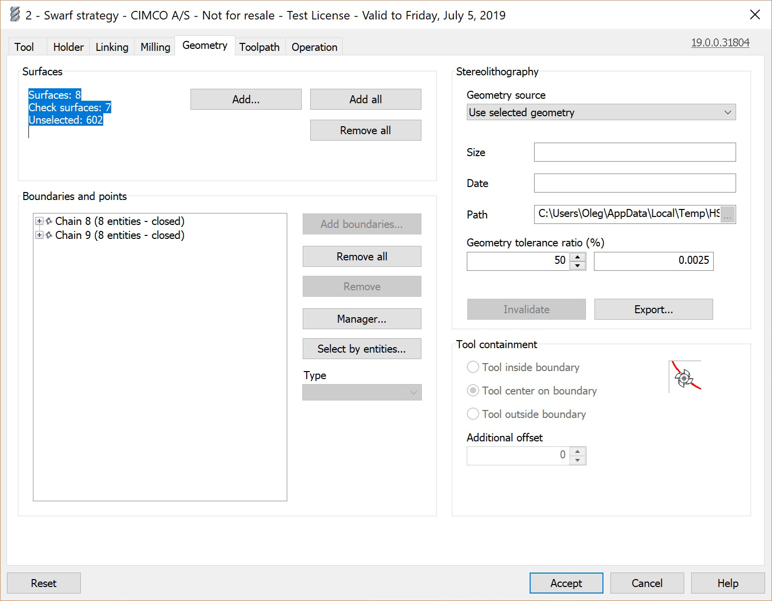
Add...
Click the Add... button to select the specific surfaces that should be machined by this operation.
Add all
Click the Add all button to select all surfaces to be machined by this operation.
Remove all
Click the Remove all button to remove all surfaces from the selection and so they are not machined by this operation.
Boundaries and points
The list Boundaries and points shows the boundaries and points for the operation. Boundaries and points can be added or removed by using the buttons Add boundaries... or Remove all.
Add boundaries
The Add boundaries... button allows the user to add one or more points or boundaries to the operation.
Remove all
The Remove all button removes all boundaries and points from the operation.
Remove
The Remove button only removes the selected boundary or point from the operation.
Manager...
The Manager... button enables you to switch to the Mastercam chain manager, and allows the boundaries or points to be edited there.
Select by entities...
The Select by entities... button changes to the graphics window, where the user can select an entity. The boundary containing that entity (if any) is then selected.
Type
From the dropdown menu Type, the type of boundary can be selected. The available options are Bottom and Top.
Bottom
Specifies bottom curve for Swarf.
Top
Specifies top curve for Swarf.
The available options for points are:
Entry
Home
Geometry source
From the dropdown menu Geometry source, the source of the geometry can be selected. The following options are available:
Use selected geometry
The option Use selected geometry generates the triangulation model for the toolpath generation from the selected geometry.
Use STL file
The option STL file lets you select an STL file which will be used for the toolpath generation. This can be particularly powerful when very large files are used, for which triangulation takes a long time. In this case a pre-generated STL file avoids lengthy re-calcuations. Note however, that it may be dangerous to use an external STL file since this will not automatically reflect any changes made to the CAD model.
Size
The field Size contains the file size of the STL file.
Date
The field Date contains the creation date of the STL file.
Path
Use the field Path to select the location of the STL file in your file system or define where the temporary STL file should be stored.
Geometry tolerance ratio
The Geometry tolerance ratio (%) defines the fraction of the operation tolerance (specified in the toolpath tab) used for generating the STL. The remainder is used for generating the toolpaths from the STL. This setting is ignored when using an external STL file. If the tool is very small, this value should be lowered to ensure that filets are represented correctly by the STL, and for complex parts, it is sometimes possible to reduce the calculation time by reducing this value.
Invalidate
The Invalidate button causes a new STL file to be recalculated at the next regeneration, regardless of the file policy setting.
Export
The Export button exports the current STL file to an external STL file for use in other programs or for comparison in verification.
The Toolpath tab contains parameters needed for configuring the toolpath and for properly executing it on a CNC machine, such as arc filtering and other toolpath filters.
|
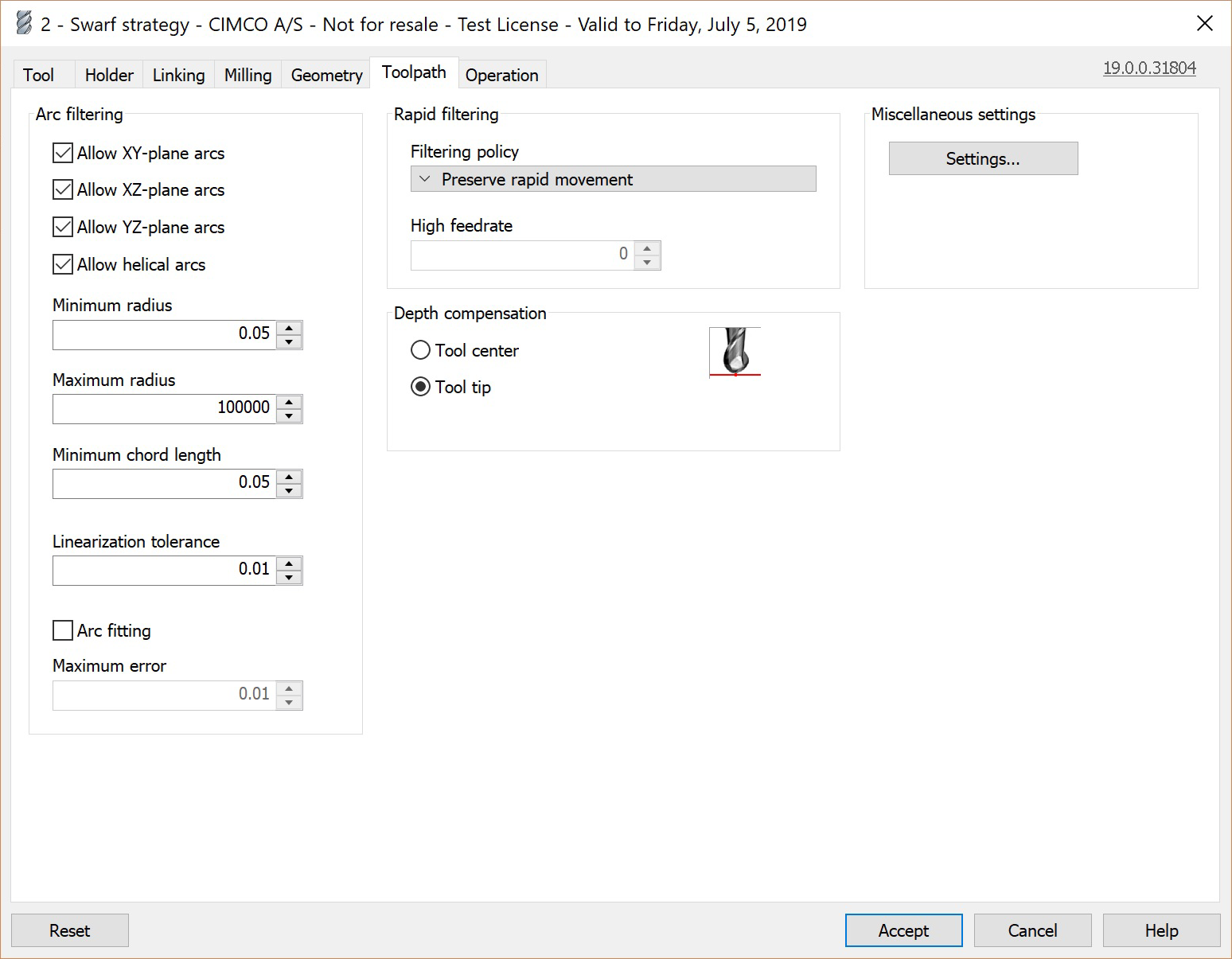
Arc filtering
The checkboxes under Arc filtering let you configure in which planes (XY-plane, XZ-plane, YZ-plane or helical arcs) arcs should be output to the machine as actual arcs (i.e. G2/G3), instead of being output as line segments (G1).
Minimum radius
The Minimum radius defines the radius below which an arc is output as line segments.
Maximum radius
The Maximum radius defines the radius above which an arc is output as line segments.
Minimum chord length
The Minimum chord length defines the arc chord length below which an arc is output as line segments.
Linearization tolerance
The Linearization tolerance is the tolerance used when arcs are to be converted to line segments, either because arcs are disallowed in that plane, or because the arc is too large or too small.
Arc fitting
Use the option Arc fitting to fit arcs where it is possible.
Maximum error
Defines the maximum error (distance) of the arc fitting to the geometry.
Filtering policy
Rapid filtering defines when rapid moves should be converted to linear moves (G1 in ISO code) at a high feed rate. The following filtering policies are available:
Preserve rapid movement: Rapid moves are always output as rapid moves (G0 in ISO code), even if they are in all three axes simultaneously. This option should only be selected if rapid moves on the machine are synchronized as linear moves.
Preserve Z-axis and XY-plane rapid movement: Rapid moves are output as rapid moves (G0 in ISO code) if they are along the Z axis or in the XY plane, but are converted to linear moves (G1 in ISO code) at a high feed rate if they are in all three axes.
Preserve vertical rapid movement: Rapid moves are output as rapid moves (G0 in ISO code) if they are vertical (i.e. along the Z axis), and are otherwise converted to linear moves (G1 in ISO code) at a high feed rate.
Preserve horizontal rapid movement: Rapid moves are output as rapid moves (G0 in ISO code) if they are horizontal (i.e. in the XY plane), and are otherwise converted to linear moves (G1 in ISO code) at a high feed rate.
Preserve one axis rapid movement: Rapid moves are output as rapid moves (G0 in ISO code) if they are in one axis only, and are otherwise converted to linear moves (G1 in ISO code) at a high feed rate.
Map to high feed cutting: All rapid moves are converted to linear
moves (G1 in ISO code) at a high feed rate.
High feed rate
High feed rate defines the feed rate used when rapid moves (G0 in ISO code) are converted to linear moves (G1 in ISO code).
Depth compensation
Depth compensation lets you choose in which way the toolpath should be vertically adjusted to the tool radius. The following options are available:
Tool center
The output toolpath corresponds to the path of the tool center.
Tool tip
The output toolpath corresponds to the path of the tool tip.
Miscellaneous
The Settings button opens up the Mastercam dialog for setting the miscellaneous values.
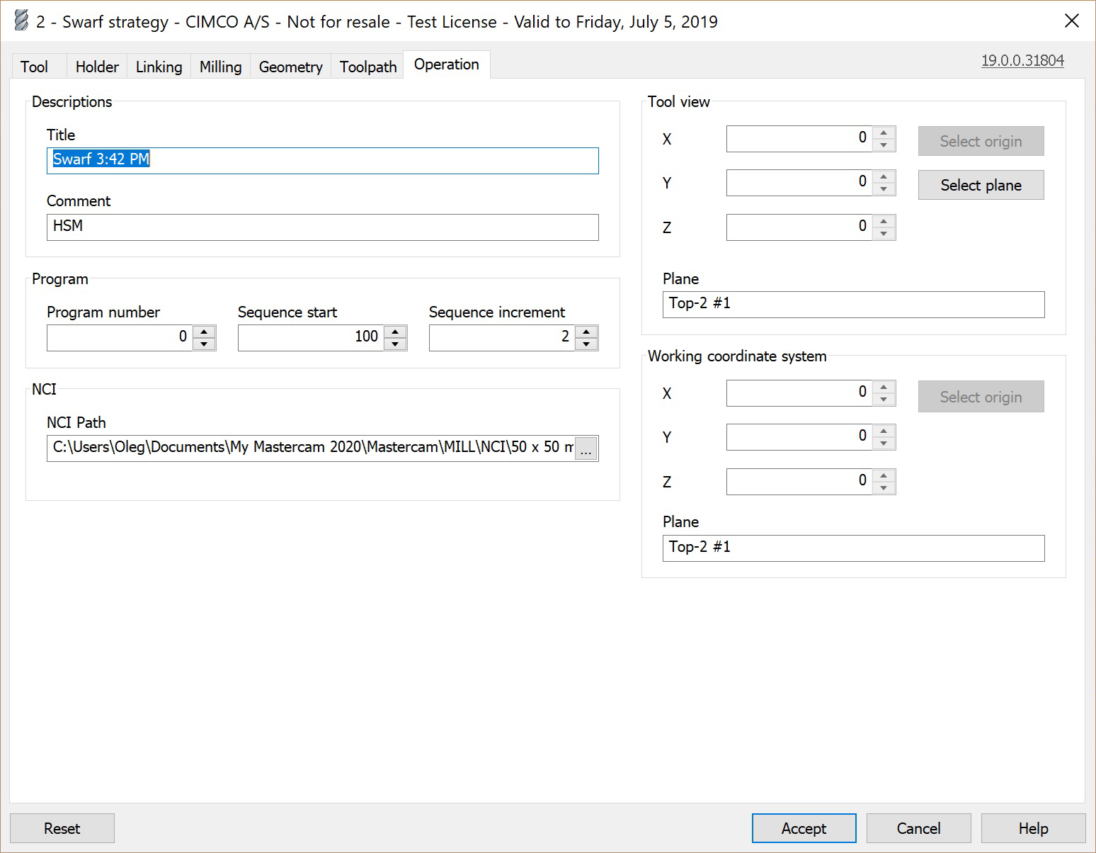
The Operation tab lets you define important parameters for the execution of the toolpath on the machine. For example, you can set the file name of the output NC file, define the working coordinate system, or configure the line numbering of the output file.
|
Title
In the Title field you can define the name of the operation as it will be displayed in the Operation manager of Mastercam.
Comment
The Comment field lets you add an additional description of your machining strategy, and can be used to further document parameters, purpose etc. of the operation.
Program number
The field Program number lets you give the output NC program a number.
Sequence start
Sequence start defines the starting line number of the output NC program.
Sequence increment
The Sequence increment defines the increments in the line numbering of the output NC program.
NCI path
In the field NCI path you can define the name and path under which the output file should be saved. Click the icon [...] in the field to browse your file system for a desired directory.
Tool view
The parameters under Tool view define the tool plane and origin for 5 axis positioning.
You can define the X, Y and Z coordinate of the tool view through the respective fields. Furthermore, you can select the origin and select the tool plane by clicking on the respective buttons.
Working coordinate system
The parameters under Working coordinate system defines the working coordinate system used in the operation.
You can define the X, Y and Z coordinate of the working coordinate system through the respective fields. Furthermore, you can select the origin by clicking on the respective button.